OFFSHORE GEOTECHNICS - for Engineers
OFFSHORE GEOTECHNICS - for Engineers |
|
|
|
|
|
HOME
Kinematics Dilatancy Angle |
Offshore Geotechnical Engineering |
|||
|
Updated 15.05 2016 On this homepage, you will find a few brief descriptions of geotechnical problems which I find particularly interesting. I find limit analysis to be very useful when doing geotechnical design and I therefore shared a few words on kinematics in geotechnical engineering. Also, you will find a video performed on Norwegian quick Clay along with a description of the geological origin of quick Clay. I hope you'll find the content interesting. Limit Analysis- Great Geotechnical Engineering approach General In the good old days of geotechnical engineering, a limit analysis solutions was frequently used to determine the capacity of a foundation. Nowadays, finite element software is used so frequently that many geotechnical engineers have forgotten how to use of limit analysis for geotechnical applications. Limit analysis consists of two approaches, one for kinematics and one, for static. I would like to pollute the Internet with a few words on kinematic admissible solutions for geotechnical engineering. kinematic admissible solutionA kinematic admissible solution is a guess on how I foundation will fail. The kinematic Admissible solution is per definition an upper bound solution. That means that if your guess the correct failure mechanism, your result will be correct. If your guess is wrong, your guess will be higher than the correct solution. My guess
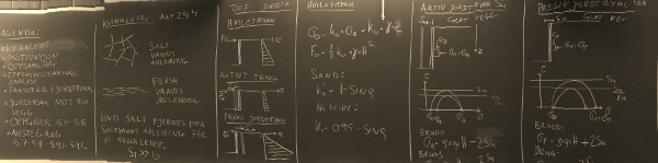
I have made a guess on a failure mechanism as seen below for a foundation with the width B and an inclined load F. I have guessed that the failure mechanism consists of a cirkular slip line. The center of the cirkel is a variabel. The center follows the function y = -kx where x and y are defined on the Figure below. k is a konstant and x varies between -B/2 to 0. The soil consistent of clay with undrained shear strength su. This solution is a variable of the classic cirkular failure mechanism, which NGI uses in their logo. I have not been able to find this problem solved by anyone else; However, I'm sure someone must have. 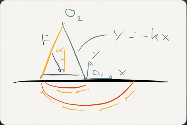
Solution found with vitual work
The foundation capacity is found with use of virtual work. I won't spend any time discussing what I did other than to mention that even
virtual work might be hard work, dispite its virtualism (geotechnical engineering humor). The solution:
Minimizing energy
The capacity of the foundation F is minimum of the equation above for any alpha. In other words, we determine the capacity of
the foundation for any angle of the load. This can be plotted by splitting F in a vertical and a horisontal component.
If you were to assume that B equals 1 and su is equal to 1, then you may plot F as a function of alpha. I have done so below.
Stability Envelope
The graph above illustrates the stability envelope for the foundation. I have now illustrated how a
kinematic admissible solution may be used to determine the stability of the foundation.
Compared to the DNV 30.4 solution my kinemtic solution is relative good.
Geotechnical design of GRP CoversGeneral
GRP covers are made of glass fiber reinforced plastic and are commonly used in the North Sea
for protection of infrastructure on the seabed. Most commonly, the GRP covers are supported
by rock dump. Depending on the water depth, hydrodynamic loading will be the governing load case
or alternatively trawl net loads.
Geotechnical engineering of GRP covers
The limit equilibrium method is used for the geotechnical design of the GRP covers.
A series failure mechanisms are considered to find the correct capacity of the geotechnical problem.
The geotechnical design is particularly complicated when the GRP cover is placed on very soft clay.
To verify the geotechnical design, it is recommended to complete the analysis with use of LimitState:geo. It is a great new tool which uses kinematics. Check out their homepage where I have posted the following link: LimitState:Geo.
|
|||
Pipe Soil InteractionGeneralPipelines, flexibles and umbilicals are installed by Subsea 7. As part of the installation analysis, a geotechnical
assessment of the pipe-soil interaction is performed. Check out the pipe soil interaction link above.
Trenched productsPipelines, flexibles and umbilicals are often trench by either jetting or ploughing. DNV-RP-F110 does provide geotechnical approaches on how to determine uplift resistance and downward resistance for trenched pipes; however, no appropriate recommendations are given for lateral resistance of trenched pipelines. Subsea 7's geotechnical team has developed approaches to assess lateral resistance. Rock dumped productsOn soil inappropriate for trenching, rock are typically installed for the protection of pipelines. Rock dump consist of crushed rock from quarries and generally has a particle size between 1 inch and 5 inch. No geotechnical design codes or papers seem to have appropriate methodologies described to assess pipe-soil interaction in a rock dump. Subsea 7's geotechnical team has developed approaches for the geotechnical assessment of a rock dumped pipeline. |
|||