Kinematic Admissible Solution - limit analysis
Kinematic Admissible Solution - limit analysis |
|
|
|
|
|
HOME
Kinematics Dilatancy Angle |
Kinematic Admissible Solution |
|||
|
Updated 15.05 2016 General In the good old days of geotechnical engineering, a kinematic admissible solution was frequently used to determine the capacity of a foundation. Nowadays, finite element software is used so frequently that many geotechnical engineers have forgotten how to use a kinematic admissible solution. I would like to "reintroduce" limit analysis in geotechnical engineering to the Internet with a few words on kinematic admissible solutions for geotechnical engineering. Kinematic admissible solutionA kinematic admissible solution is a guess on how I foundation will fail. The kinematic Admissible solution is per definition an upper bound solution. That means that if your guess the correct failure mechanism, your result will be correct. If your guess is wrong, your guess will be higher than the correct solution. My guess
I have made a guess on a failure mechanism as seen below for a foundation with the width B and an inclined load F. I have guessed that the failure mechanism consists of three triangles. Two of the triangulars have 60° in each corner and the third is a function of theta. The soil consistent of clay with undrained shear strength su. I have not been able to find this problem solved by anyone else; However, I'm sure someone must have. 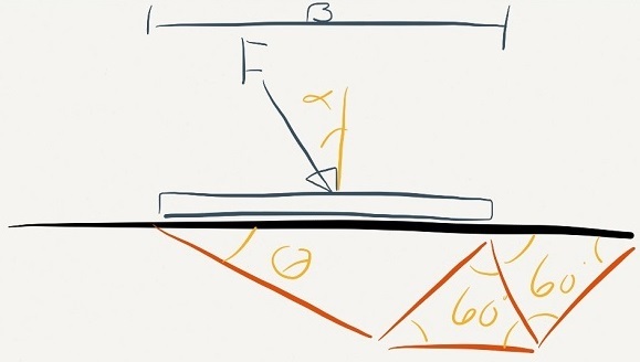
Solution found with vitual work
The foundation capacity is found with use of virtual work. I won't spend any time discussing what I did other than to mention that even
virtual work might be hard work. The solution:
Minimizing energy
The capacity of the foundation F is minimum of the equation above for any alpha.
I have plotted the F as a function of alpha and thanks to my friend Stobbe - the software engineer - you are able to input B and Su below.
Stability EnvelopeThe graph above illustrates the stability envelope for the foundation. I have now illustrated how a kinematic admissible solution may be used to determine the stability of the foundation. Compared to the DNV 30.4 solution my kinemtic solution is relative good. Limit analysis - a strong geotechnical toolGeneral
Limit analysis have been a preferred design methodology in Denmark since Brinch Hansen for ULS design.
There are two options in limite analysis; kinematic admissible solution or a static admissible stress distribution.
With some effort, the kinetic admissible solution is suited for hand calculation of all geotechnical problems related to ultimate capacity assessment, especially for fast estimates on complicated problems.
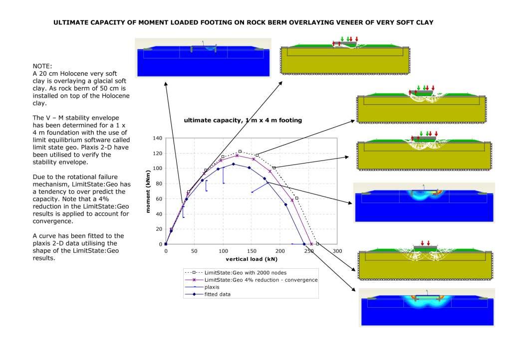
Identification of stability envelope utilizing limit state analysis
Utilizing LimitState:Geo to accurately predict the ultimate capacity has proven to be excellent tool for geotechnical
design. The software can easily be used determine the stability envelope for all geotechnical problems. The figure below
illustrates the stability envelope for a foundation placed on a rock berm installed on top of very soft clay veneer.
|
|||