|
Updated 26.04 2020
The dilatancy angle is one of the most misunderstood geotechnical parameters – and for good reason. In fact, I may not fully have understood it perfectly myself, but I will in this section make an attempt to explain the dilatancy angle.
First of all, a material that dilates during failure, will not move the same direction as the load is applied. This is because the material expands a little at failure, this is seen in the illustration below.

For a foundation on a flat soil subject to a horizontal load on a material that has a dilatancy angle, then the foundation is anticipated to lift of the ground during failure, see below:

Having a soil where the friction angle PHI is equal to the dilatancy angle PSI means that the soil will dilate during failure. This is called associated flow. The opposite is a nonassociated flow where the PSI can be equal to 0. When PHI is equal to 0, then a foundation on the soil subject to a horizontal load will displace along the surface – and not lift of the ground.

So, what is this PSI for a given geotechnical problem? If a laboratory test is completed, then the PSI is often found equal to Phi – 30deg. Also, if you want to predict the displacements of the of a foundation then you will find that PSI should be 0 or PHI – 30deg. However, the problem then occurs for Ultimate Limit State ULS design. When the bearing capacity of a foundation is assessed with use of the bearing capacity equation, then few realize that the bearing capacity is based on PSI equal to PHI.
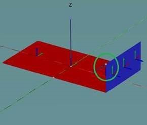
If you in a numerical problem want to assess the bearing capacity and you use PSI equal to 0, then you will obtain results of sin(PHI), rather than tan(PHI). I can not provide a simple proof for this, but if we imagine that the box will either slide along the plane or lift of the plane, then we can see that some work is missing for the case where the box slides along the plane. You can find this difference of sin(PHI) and tan(PHI) if you run a problem with a load leading to both overturning and torsion in PLAXIS 3D, see the Figure below:

If you run two models, one with PSI equal to PHI and one with PSI equal to 0, then you will find the difference of sin(PHI)/tan(PHI).
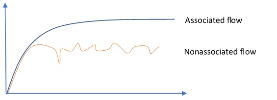
If you model PSI equal to 0 in FEA software, you may also find that it can be difficult to obtain a flat curve for the load displacement curve. This can be interpreted as numerical problems; however, it is more likely that this is because a problem where PSI is less than PHI can have more solutions to the problem. Therefore, the software, may find it difficult to determine the solution to the problem – since there are more solutions. This is illustrated below. For more info, it is recommended to read the Optum G2 Theory manual.

So what does this mean in practical term, if you use psi = phi you will get the correct bearing capacity but wrong collapse mechanism. If you instead use PSI < PHI and get the correct collapse mechanism but the wrong bearing capacity.
I would recommend to use PHI = PSI for ULS and the actual PSI (along with perhaps an increased fictitious PHI) for SLS. hope this article has managed to give some insight into the interesting topic of dilatancy angles in design. I will admit that the subject is very comprehensive and may not have been explained in sufficient detail, but more as an introduction.
Finally, should you find the subject of dilatancy angle and the effect on bearing capacity, then I have a proposal for a master thesis. Please contact me for more details.
|

